




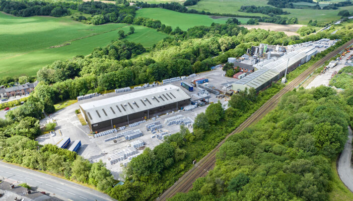

Search our document section below where you will find IKO Products Brochures, Technical Data Sheets, BIM files, BBA certification, TDS documents and Case Studies showing full details of IKO installations.
For DECLARATION OF PERFORMANCE DOCUMENTS please visit ikodop.eu.
Please contact us if you require any further assistance or product information.



| Filename | IKO Guidance document on Flat roof Decks JAN 2020 .pdf |
| Filesize | 558.25 KB |
| Version | 1 Previous versions |
| Date added | February 3, 2020 |
| Downloaded | 1460 times |
| Category | Technical Briefing Documents |
Disclaimer
Whilst every precaution is taken to ensure that the information given in this literature is correct and up to date it is not intended to form part of any contract or give rise to any collateral liability, which is hereby specifically excluded. IKO reserve the right to amend and/or withdraw this document without notice. Users of published guidance for the installation of IKO materials should therefore verify with the company whether any changes in our specification, application details, withdrawals or otherwise have taken place since this literature was issued.
Structural Deck
The structural deck provides the primary support for the roofing system. It must resist dead, live and wind loads, including storms. It must also be suitable for the proposed roofing system, and subsequent use.
Relevant structural and loading codes for each material must be followed for, and the requirements of the current building regulations must be checked and observed. Resultantly, a structural engineer should be consulted to confirm compliance.
Dead and imposed loads upon a roof should be assessed in accordance with BS EN 1991-1-1 +UK National Annex taking due consideration of any added surface; green roof, paving, gravel, blue roof water retention, etc.
Snow loads should be assessed in accordance with BS EN 1991 -1 – 3 + UK National annex. Wind loads should be assessed in accordance with BS EN 1991 -1 – 4 + A1: 2010 + UK National annex.
Note: for relevant structural material on roof structure strength and stiffness, see BS EN 1992-1-1, BS EN 1993 -1 -1, BS EN 1994 1-1, BS EN 1995 1-1, BS EN 1999 1-1 and their UK National annex.
Note: If the use of the roof is to be changed, the suitability of the deck and the structure must be reconfirmed.
The deck may also be laid or fixed so as to provide a suitable fall for drainage of the roof surface, as required in the current BS6229 Code of Practice for flat roofs with continuously supported coverings.
Working on any roof is a hazardous activity, irrespective of whether it is fragile or non-fragile. Work on roofs with such decks need a careful risk assessment agreed before commencement.

OSB/3 or OSB/4 Decks
OSB/3 or OSB/4 used for roof decks should be 18mm thick.
OSB/3 or OSB/4 panels for roof decks must be CE marked in accordance with BS EN13986:2004. This standard is a technical specification for wood-based panels which implements the provisions of the Construction Products Regulation (CPR) In addition to the CE mark, OSB/3 that is certified by the British Board of Agrément (BBA) is permitted for structural use by NHBC (UK)
OSB/3 or OSB/4 conforming to BS EN 300: 1997 is deemed suitable for flat roofing would be identified on each board facing.
Design of the roof structure and installation of the panels should be carried out in accordance with BS EN 1995-1-1:2004, DD CEN/TS 12872:2007 or BS 8103-3:2009, as appropriate according to the type of construction.
The panels should be supported at not more than 600mm centres with noggins or bearers to support edges. Long edges should be at right angles to the joists. 15mm OSB/3 could be used where the deck is supported on joists at 450mm centres
A 3mm expansion gap should be provided between the panels, which should be fixed to the joists at 100mm centres using 50mm x 10g ring shank nails which should be knocked home to provide a flush finish.
All decks should provide finished falls as required by BS6229 to achieve a minimum fall of 1:80. This may be undertaken by the use of timber firring pieces fixed to each joint support beneath the OSB deck, or by the use of tapered insulation.
Plywood Decks

Plywood panels for roof decks must be CE marked in accordance with BS EN13986:2004. Plywood suitable for flat roofing would be marked BS EN 636-2 or BS EN 636-3 and must be suitable for exterior use.
Design of the roof structure and installation of the panels should be carried out in accordance with BS EN 1995-1-1:2004, DD CEN/TS 12872:2007 or BS 8103-3:2009, as appropriate according to the type of construction.
The panels should be supported at not more than 600mm centres with noggins or bearers to support edges. Long edges should be at right angles to the joists. 15mm OSB/3 could be used where the deck is supported on joists at 450mm centres
A 3mm expansion gap should be provided between the panels, which should be fixed to the joists at 100mm centres using 50mm x 10g ring shank nails which should be knocked home to provide a flush finish.
All decks should provide finished falls as required by BS6229 to achieve a minimum fall of 1:80. This may be undertaken by the use of timber firring pieces fixed to each joint support beneath the plywood deck, or by the use of tapered insulation.
Timber Board Decks
Timber boarding suitable for roof decks should be 19mm nominal thickness, planed and closely clamped together, tongued and grooved or closely butted.
Where using this type of deck then it will be necessary to first install a random nailed isolating layer prior to the installation of the main roofing system to cover the joints between adjacent boards. This decking is not suitable for hot melt or cold liquid applied systems.
The panels should be supported at not more than 600mm centres with noggins or bearers to support edges. Long edges should be at right angles to the joists.
The boards should be securely clamped and fixed to the joists at 100mm centres using suitable exterior wood screws or shank nails which should be knocked home to provide a flush finish.
Profiled Metal Decks
Profiled metal decks that are to support Built Up Roofing systems and their components, should be of a suitable profile where the crowns that are wider than the troughs. The trough span should not exceed 150mm, otherwise the vapour barrier may sag at the laps and adequate support will not be provided or the insulation.
Metal roof decking minimum thickness 0.7mm for galvanised steel to BS EN 10147: 2000 or 0.9mm for aluminium to BS EN 485-2: 1995 (or 1.2mm where the roofing system is being mechanically fastened into the aluminium deck) being installed in strict accordance with the manufacturers’ instructions.
The lightweight construction has the advantage of being able to cope with very long spans, enabling large room spaces to be created and reducing the load on the building’s structure.
The decking should be designed in strict accordance with the Metal Roof Deck Association “Code of Design and Technical Requirement for Light Gauge Metal Roof Decks.” as well as being capable of supporting any dead and live loads acting upon it.
Profiled metal decking does not provide a continuous supported surface and therefore can only be used when supporting a timber deck or rigid insulation which can then be covered with a waterproofing membrane.
The Vapour Control Layer must be fully bonded to the crowns of the metal deck which must be a minimum 49% of the total surface area.
Concrete Decks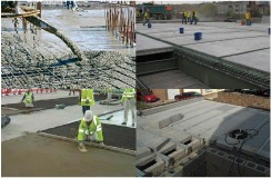
Types:
• Insitu cast concrete (typically 150mm thick)
• Precast concrete panels
• Beam and block
Once the substrate has cured and prior to the application of any waterproofing layer an adhesion test must be undertaken at regular intervals (50m²) to ensure a suitable bond and adhesion can be achieved with the new proposed waterproofing system.
Concrete and Screed Surface Finishes
Before priming and application of the new waterproofing system, the concrete/screed surfaces must be smooth and level, protrusions such as aggregate or float ridges should be ground down.
The surfaces must be clean and dry, free from surface water, ice, snow or frost, dust, dirt, oil, grease, curing compounds or any foreign matter detrimental to the adhesion of the new waterproofing. Any scaling or latent concrete must be removed.
Voids, cracks, holes, honeycombs and other damaged horizontal or vertical surfaces must be repaired before application of the waterproofing.
All decks should provide finished falls as required by BS6229 to achieve a minimum fall of 1:80. This may be undertaken by the use of a suitable cementitious screed, or by the use of tapered insulation.
Concrete Drying Process
An indication of how slow the drying out process is can be gained from BS8203, which uses the rule of thumb that a screed will dry at approximately 1mm per day from one face. In well vented conditions with reduced drying rates as the process continues, such that a 50mm screed will take 2 months. The equivalent time for a slab 150mm thick is much slower and may take near 1 year to dry.
Preparation of Concrete Substrates
Concrete Substrates:
New concrete will result in Laitance forming on the top surface of the concrete resulting in the lack of bond with the waterproofing this laitance must be removed. Laitance is an accumulation of fine particles on the surface of fresh concrete due to an upward movement of water that result in a ‘crust forming on the top surface of the concrete which will inhibit any bond of the waterproofing, this layer of laitance must be mechanically removed and an adhesion test undertaken.
So, what is laitance?
laitance is a weak, easily-crumbled layer on the surface of concrete and concrete screeds, consisting of cement and fine aggregates that rise to the surface when too much water is added. That result in a ‘crust forming on the top surface of the concrete which will inhibit any bond of the waterproofing, this layer of laitance must be mechanically removed and an adhesion test undertaken. Laitance may also be caused by overtrowelling, rain damage, or poor curing.

Laitance will dust very easily. Simply run your hand across a new slab will scuff it up.
Laitance is always present on new concrete – but unfortunately, age is no guarantee that it’s not present, unless it has been removed by previous surface preparation. The laitance layer may look like nothing more than fine dust, or it can reach a depth of several millimetres or more.
How do I test for laitance?
Here’s the highly technical answer: scrape the surface of your concrete floor with a knife. “If a powdery material can be scraped from the surface, excessive laitance is present,” To get a sense of how thick the laitance is, “Score the surface of the substrate with a steel edge until the main aggregate is reached,”
Then, how do I remove it?
There are several ways to remove laitance. The method depends on how much area the laitance is covering, how thick the layer is, and how detailed your work needs to be.
If laitance is thicker, mechanical planing may be preferred. Surface planers, also called scarifies or milling machines, remove the layer faster and more aggressively because “they use the pummelling action of multi-tipped cutting wheels that rotate at high speeds to chip away at the surface
Cast in Situ concrete
Cast in situ concrete is where the concrete is delivered to site that is poured into a supporting former.
• Requires typically 28 days curing for any waterproofing can be applied.
• Construction water must be drained by forming temporary drainage holes through the slab as specified in BS 6229.
• Difficult to lay to falls
• Cure creates hollows and depressions, voids, cracks, holes, honeycombs that will need rectifying prior to the installation of any waterproofing.
• Surface finish must have a smooth wood float/easy float uniform finish and free from projections
• Requires formwork to create the mould to form the concrete structure.
• Common for roofs and podiums where waterproofing is suitable on zero falls.
• May require a screed where the surface is not sufficiently smooth/even.
• Apply a suitable cementitious screed as necessary to achieve a minimum finished fall of 1:80.
• The surface of the deck/screed should be sufficiently cured and dried before the commencement of any roofing works.
• Before priming and application of the new waterproofing system, the concrete substrate shall be clean and dry, free from surface water, ice, snow or frost, dust, dirt, oil, grease, curing compounds or any foreign matter detrimental to the adhesion of the new waterproofing.
• Any scaling or laitance concrete must be sandblasted/scarified off
Precast concrete panels and beam and block
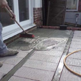
Precast concrete slabs are preformed off site slabs within factory conditions
• Manufacturing control less prone to defects
• Pre made to size and delivered to site
• Requires no formwork
• Easy to handle
• Site formed jointing
• Can be installed to a fall
• May require a screed topping
Beam and Block
Beam and block are where a preformed concrete beam support structure is infilled with cement/brick blocks to create a suspended slab/deck.
• Requires a screed topping to fill all the joints.
• Easy to handle and lightweight.
• No formwork required
• Quick and easy to install.
Apply a suitable cementitious screed as necessary to achieve a minimum finished fall of 1:80, or where the surface is not sufficiently smooth/level. The screed should be sufficiently cured and dried before the commencement of roofing works.
Aerated autoclaved concrete (AAC or “Siporex”) can have the appearance of reinforced or precast concrete units. However, this material is fragile, and suitable precautions should be taken. Attention is drawn to Health and Safety Executive publications HSG33 and Health and Safety in roofing.
Adhesion and Moisture Reading Test
The whole roof area, where the waterproofing is to be applied is to be prepared in accordance with the specification. Substrates will vary in terms of the specific requirements to test the area for:
• Adhesion test.
• Moisture content
All substrates must be clean, dry and free from grease, curing compounds, laitance, dirt, silt and other contaminants. Any irregularities and loose material or other condition that may be detrimental to the adhesion to the substrate must be removed prior to undertaking any test area.
Adhesion Tests
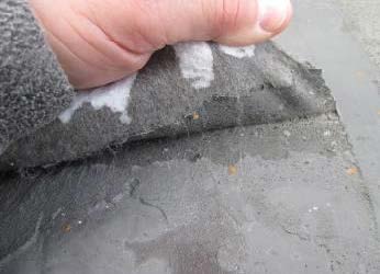
An adhesion test is done to determine substrate compatibility. A key attribute for waterproofing overlays is the bond achieved between the substrate and first waterproofing layer.
IKO recommends test procedures outlined below be performed on roofs prior to the application of any IKO waterproofing system. Running these tests will help ensure that the waterproofing will adhere properly once installed
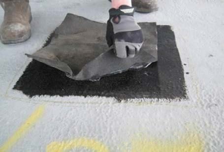
Ideally, substrates need to be free of moisture, debris and contamination before the adhesion tests. To test for cleanliness, press a 100mm long piece of 50mm tape to the cleaned and dried roof using hand pressure. Then, peel the tape off the roof. If it comes off easily, and or is laden with dirt, degraded roofing material and other particulates, the roof is not cleaned satisfactorily. Re-clean and dry the roof and repeat this test. This test should be conducted in several areas around the roof, especially in ponded or other dirty areas


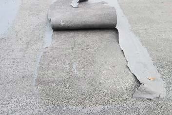
Scarifying the concrete surface to remove the laitance is required before a test area can be undertaken.
Area should be primed with the specified primer, allowed to dry thoroughly prior to the application of the specified first waterproofing layer. Allow to cool and cure before undertaking the pull off test.
Moisture Reading of Substrates:
Concrete, screeds, masonry and brickwork surfaces should be smooth and flat. Any raised areas or protrusions must be mechanically removed and areas filled to a flush finish as required. New concrete surfaces must be cured for a minimum of 28 days prior to application of the waterproofing first layer.
The substrate shall have a maximum moisture content of 6% or 75% relative humidity, and be prepared as required to provide adhesion of the system to the substrate with a minimum bond strength of 116 psi (0.8 N/mm2). Determinations of adhesion, bond strength and moisture content shall be performed periodically by the contractor throughout the course of work at locations over the whole area to be waterproofed.
Moisture readings can be undertaken by using a Tramex CME4 concrete moisture meter.

 .
. .
.